| |
| Services |
 |
|
| 1. Greenfield or new water treatment plants based on Tube Settler technology / clarifiers read more... |
| 2. Single or multimedia gravity filter beds. read more... |
| 3. Complete water treatment systems and Water supply schemes read more... |
| 4. Augmentation or retrofit of existing plants for capacity or quality up-gradation read more... |
5. Mass application of small capacity standardized plants
read more... |
| 6. Sewage Treatment Plant. |
| 7. Project Management Consultancy. (PMC).. |
| 8. Civil, Structural, Electrical & Automation Engineering design & drawings. |
|
| Research Paper & Presentation |
|
| |
|
|
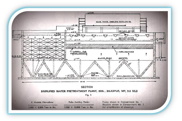
| Simplified Pretreatment Plant of 9.0 M.L.D. Capacity
at BBIL Paper Mills, Bilaspur, M.P. |
| |
|
|
| 2. |
Design and Construction: |
|
|
| |
Hydraulic & Process designs for the 9.0 mld capacity plant were adopted from high
rate, non-mechanical, Simplified treatment technology developed by Dr. J.N. Kardile
Fellow IWWA. The plant consistes of following units. |
| |
|
| |
| 1] |
Stilling chamber and mixing channel. |
|
|
| 2] |
Alum mixing and dosing tanks. |
|
|
| 3] |
Non-mechanical flocculation tanks. Size 3.5m x 5.0m ht each, Two in number. |
|
|
| 4] |
Tube settling tanks. Size 3.5m x 10.5m x 3.5m ht each, Two in number. |
|
| |
|
| |
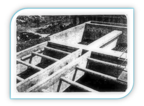
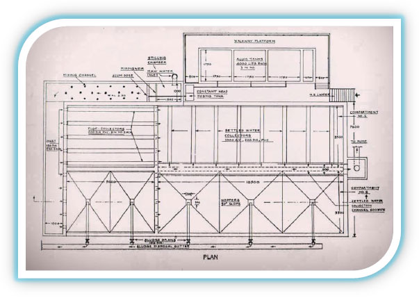
Filters were not provided as the requirement of treated water turbidity was 20
ppm. Photograph of plant (no. 1) and detailed layout drawings (Fig. 1) are enclosed in
the article.
All the processes from mixing upto sludge disposal are of non-mechanical type
and no mechanical equipments used in the entire process. The plant is constructed in
R.C.C. and is provided with raft foundation. |
| |
 |
| |
| 2.1 |
Stilling chamber and mixing channel: |
| |
|
| |
Raw water which is pumped from the river Arpa is introduced into a hopper bottom
stilling chamber of size 1.0m x 2.0m. A mixing-cum-measuring weir of 0.4m ht is
provided on the outlet side of chamber. Alum dose is introduced on the down-stream
side of weir through a perforated PVC pipe in the maximum zone of turbulence to have
effective hydraulic mixing. Mixing channel (1.0m wide) is provided with 75mm dia. A.C.
pipe pieces (200 mm ht) embedded in bed concrete to enhance coagulation action. |
| |
|
| 2.2 |
Alum mixing and dosing tanks: |
| |
|
| |
Three alum mixing tanks of size 1.75m x 1.75m x 1.5m ht. of effective capacity 4000
litres each, are provided on a separate structure to feed the alum solution by gravity to
the dosing tank and further to the mixing channel. Alum solution is prepared by a nonmechanical
mixing arrangement and is then fed to the constant head dosing tank, from
which it is introduced in the perforated PVC feeding pipe on the down-stream side of
mixing weir. |
| |
|
| |
 |
| |
 |
| |
|
| 2.3 |
Non-mechanical flocculation tanks: |
| |
|
| |
Two hopper bottom tanks of size 3.5m x 5.0m x 3.5m ht above hoppers are provided
in parallel. Two hoppers are provided in each tank with minimum wall slope of 50
degrees to drain out deposited sludge periodically, by hydrostatic pressure. The
coagulated water is introduced at the top from mixing channel through five numbers of
150mm dia openings in eachtank. The water flows in the downward direction through a
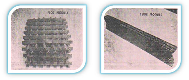
recently developed flocculation media known as �K floc modules� for 2.0m depth and
covering all the area. Floc modules are fabricated out of PVC angles of size 50mm x
50mm and are of 1.5mm thickness. Size of each module is kept 1.0m x 1.0m x 0.5m ht for
easy fabrication and handling. One module consists of twelve layers of the PVC angles
(Photograph below). Angles are arranged in parallel with certain gaps in a layer. Two
adjacent layers are laid in cross-wise directions to each other. The angles in every
alternate layer are arranged in such a way so as to cover the gaps in the alternate layers.
All the angles are tied together by copper wire. Thus, a floc module is flexible in nature. It
can be easily handled, transported and can be stacked above each other to gravel bed
flocculator. It has following advantages over gravel bed flocculator. |
| |
|
| |
| a] |
Uniform porosity can be maintained throughout the depth of flocculation medaia. |
|
|
| b] |
Porosity of required dimensions can be designed by changing the size of PVC
angles and gaps. |
|
|
| c] |
No sludge deposition takes place in the media because of steeply inclined smooth
angle surface. |
|
| |
|
| |
Floc modules are supported by M.S. angles frame at the bottom, which in turn rests
on side supports provided on top of hopper. Flocculated water is collected by means of
200mm dia perforated PVC pipes provided below the M.S. supporting grilles. The
perforations are designed in such a way so that floc is collected uniformly over the plain
area. The surface loading and detention time provided for this flocculator are 10.500
litres/sqm/hr and 20 minutes respectively. |
| |
|
| 2.4 |
Tube settling tanks: |
| |
|
| |
Two tube settling tanks of size 3.5m x 10.5m x 3.5m ht above hopper, are provided in
parallel after non-mechanical flocculation tanks. The flocculated water is introduced
from flocculation tanks just above the top of hopper level through five number of 200mm
dia openings in each tank. The water flows in the upward directions through a layer of
tube modules, resting on the side corbels which are provided 1.5m above hopper top.
Tube module consists of 50mm x 50mm black PVC cement solvent at 60 degrees angle,
while the adjacent layers are provided in alternate directions (photograph below.) Each
module consists of five such layers having 0.5m ht and 3.5m span. Modules are simplysupported
at ends over the corbels.
The clarified water is collected at the top, 1.0m above the tube modules by means of
uniformly spaced perforated PVC pipes of 200mm dia. From these collector pipes settled
water collection channel which is provided on the central partition wall. From the central
collection channel the settled water is then taken to the storage reservoir.
The sludge gets effectively settled during then tube settling process in the ottom
hoppers provided in the tanks. Three hoppers of size 3.5m x 3.5m each with 50 degree
side wall slope are provided in each tank. The sludge drain valves are operated
periodically to drain out the settled sludge by hydrostatic pressure. The surface loading
provided for tube settling tanks is 5000 lits/sqm/hr to get desired settled water quality. |
| |
 |
| |
|
|
| 3. |
Performance: |
| |
|
| |
The raw water turbidity during the monsoon of 1987 was normally below 500 ppm
with occasional rise upto 2000 ppm during flash flooding. The settled water turbidity
was generally found below 20 ppm with occasional rise upto 30 ppm. The sludge drain
valves were opened periodically, the opening interval depending on the raw water
turbidity. |
| |
|
| 4. |
Treatment & Recycling of Backwater: |
| |
|
| |
During severe shortage of raw water from March 1987 to July 1987, in the bed of river
Arpa, it was decided to reuse backwater from paper mills after clarification through tube
settling tanks. The rate of backwater was about 100 cubm/hr and it contained
flocculated paper fibres of bluish white colour. The turbidity of backwater was generally
found to be 2000 ppm. In order to clarify this backwater, out of the two parallel
flocculation-settling units, one unit was used for clarifying raw water from the river. For
back water clarification the floc modules were removed from the flocculator, as the
backwater was already flocculated in the paper making process. The clarified water from
both the units was allowed to mix in the central settled water collection channel and was
then taken to the storage reservoir. |
| |
|
| 5. |
Observations: |
| |
|
| |
| a] |
The settled water turbidity of backwater was generally observed in the range of 10
to 15 ppm. The process was simple to control from operation point of view as the
backwater was already flocculated and it did not require any alum dosing. Further the
turbidity of raw backwater did not vary to a great extent, during this period. The process
was found to be completely stable. |
|
|
| b] |
Sludge from backwater unit was collected in the form of paper fibres. The quantity of
paper fibre collected in this way was about 1.0 MT/day. The investigations are on to
reuse this sludge in the paper process. |
|
|
| c] |
Sludge drain valves from backwater recovery compartment were opened at intervals
of 1-2 hrs. |
|
|
| d] |
The quantity of waste water from the paper and pulp mills was reduced by half
because of the reuse of backwater from paper mills. This resulted in improved quality
waste water from the effluent treatment plant with reduced consumption of chemicals
and electricity. |
|
| |
|
| 6. |
Conclusions: |
| |
|
| |
| a] |
The cost of the entire projectof 9.0 mld capacity pretreatment plant was Rs.
8,00,000/- only, which is about 60% - 70% that of a conventional unit. |
|
|
| b] |
As all the processes are completely non-mechanical, there is very little maintenance
and operation cost compared to the conventional plant. This was one of the major
reasons for adaptation of this type of plant by BBIL. |
|
|
| c] |
Highly qualified supervisors are not required as only alum dosing and sludge draining
are to be watched periodically. |
|
|
| d] |
Due to compact nature of plant and higher surface loading rates, land requirement
was reduced by 50% as compared to the conventional plant. |
|
|
| e] |
Due to the feasibility of backwater recovery, entire new aspect was provided to the
tube settling process. The process can be now employed to treat many industrial
effluents cost effectively by this non-mechanical means. |
|
|
| f] |
Because of the recovery and reuse of backwater following advantages were achieved
by the BBIL. |
| |
|
| |
| I] |
It was possible to operate paper and pulp mill at full production level in the water
shortage period as there was less draw from river. |
|
|
| II] |
Considerable quantity of paper fibre can be recovered from backwater with good
chance of its reusability in the paper making process. |
|
|
| III] |
Reduced qualitative and quantitative loading improved the performance of water
treatment plant of BBIL factory with reduced consumption of electricity and chemicals. |
|
| |
|
|
|
| g] |
It has been decided by BBIL management to operate the entire plant for treatment of
raw water from the river during three to four months of monsoon. For rest of the year
one half of the river & other half will be used for treating back-water from the paper
mills. |
|
|
| h] |
The single simplified pretreatment unit can now be used to treat :- |
| |
|
| |
| I] |
Raw water from the river. |
|
|
| II] |
Back water from the paper mills. |
|
|
| III] |
Partially backwater and partially raw water from the river. |
|
|
| IV] |
Mix flow of raw water and backwater. |
| |
|
|
| |
(Experiments are still continued in this aspect.) |
|
| |
|
| |
The plant which was mainly constructed to treat raw water from the river also served
the cause in conservation of water from Industry at relatively very low cost, thus
showing the inherent flexibility in simplified, non-mechanical technology. This
experiment may lead to an altogether new concept in economic “water treatment and
conservation package” leading to reduction of pollutional imact on the environment. |
| |
|
| 7. |
Acknowledgements: |
| |
|
| |
| I] |
The author acknowledges the contribution of BBIL technical team especially in water
conservation aspect. The team was headed by Dr. V.V. Karnik, General Manager, Shri. U.B.
Bhattacharya Asst. Factory Manager, Shri. G.S. Chowdhary Quality Control Manager, Shri.
A.C. Somani Engineering Manager and Civil Engg. Dept. Author also acknowledges the
contribution of Shri. B.V. Phadke, structural consultant to the work. |
|
| |
|
| |
References: |
| |
|
| |
| 1. |
“Simple Methods in Water Purification” by Dr. J.N. Kardile |
|
|
| 2. |
New concepts in water purification” by Culp & Culp |
|
|
| 3. |
Surface water treatment for communities in developing countries” by Schulz &
Okum. |
|
|
| |
|
|
|
| Top |
| |
| |
|
